1. Танилцуулга
This manual is designed to assist owners in performing routine maintenance and more extensive repairs on their Peugeot 407 Diesel vehicles. It provides detailed instructions and illustrations to guide you through various procedures, ensuring proper vehicle upkeep and repair.
Figure 1.1: Front cover of the Peugeot 407 Diesel Owners Workshop Manual, displaying the vehicle model and manual title.

Figure 1.2: An internal page from the manual, illustrating the comprehensive nature of the content with images and text describing various repair processes.
2. Аюулгүй байдлын мэдээлэл
Always prioritize safety when working on your vehicle. Ensure the vehicle is securely supported on jack stands before working underneath. Disconnect the battery's negative terminal before performing any electrical work. Wear appropriate personal protective equipment, such as gloves and eye protection. Refer to the vehicle's specific safety warnings and guidelines before commencing any task.
3. Weekly Checks
Performing regular weekly checks helps maintain your vehicle's performance and identify potential issues early. Key checks include:
- Underbonnet check points
- Хөдөлгүүрийн тосны түвшин
- Хөргөлтийн түвшин
- Тоормосны болон шүүрч авах шингэний түвшин
- Дугуйны нөхцөл байдал ба даралт
- Гидравлик жолооны хүрдний шингэний түвшин
- Screen washer fluid level
- Зайны байдал
- Чийдэн болон гал хамгаалагчийн ажиллагаа
- Арчигчийн ирний байдал
4. Routine Maintenance and Servicing
Regular maintenance is crucial for the longevity and reliability of your Peugeot 407. This section covers routine servicing specifications and maintenance schedules.
4.1. Lubricants and Fluids
Refer to the specifications for correct lubricant and fluid types and capacities.
4.2. Capacities

Figure 4.1: A page detailing various specifications, including fluid capacities and torque wrench settings for different components.
| Систем | Хүчин чадал |
|---|---|
| Engine oil (1.6 litre engine) | 3.75 литр |
| Engine oil (2.0 litre engine) | 5.25 литр |
| Cooling system (1.6 litre engine) | 7.2 литр |
| Manual transmission (BE4/R) | 1.9 литр |
| Automatic transmission (AL4) | 6.0 litres (total, including torque converter) |
| Шатахууны сав | 66 литр |
4.3. Torque Wrench Settings
| Бүрэлдэхүүн хэсэг | Nm | lb ft |
|---|---|---|
| Automatic transmission drain plug (AL4) | 33 | 24 |
| Manual transmission drain plug (BE4/R) | 22 | 16 |
| Газрын тосны шүүлтүүрийн таг | 25 | 18 |
| Дугуйны боолт | 90 | 66 |
5. Repairs and Overhaul
This section provides detailed procedures for repairing and overhauling various vehicle systems, including the engine, transmission, brakes, and body equipment.
5.1. Engine In-Car Repair Procedures (1.6 litre engine exampлэ)
This subsection details procedures that can be performed without removing the engine from the vehicle.

Figure 5.1: Illustrations showing the refitting of hydraulic tappets and rocker arms, and aligning timing chain marks during engine repair.
- Refit hydraulic tappets: Ensure correct placement.
- Refit rocker arms: Position them correctly on their original locations.
- Align timing chain marks: Align the black-coloured links with the marks on the camshaft sprockets. There must be 12 chain link pins between the sprockets.
- Assemble chain tensioner: Position the chain tensioner between the upper and lower runs of the chain.
- Apply sealant to camshaft cover/bearing ladder: Ensure sealant does not enter the tensioner oil holes.
5.2. Oil Pump Removal, Inspection, and Refitting
Detailed steps for servicing the oil pump.

Figure 5.2: Images illustrating the removal of oil pick-up tube Allen screws, oil pump retaining bolts, and components of the oil pump assembly.
Устгах
- Remove the pump as described in Section 11.
- Remove the crankshaft sprocket as described in Section 8. Recover the locating key from the crankshaft.
- Disconnect the wiring plug, undo the bolts and remove the crankshaft position sensor, located on the right-hand end of the cylinder block.
- Undo the three Allen screws and remove the oil pump pick-up tube from the pump/block.
- Undo the 8 bolts, and remove the oil pump.
Хяналт шалгалт
- Undo and remove the Torx bolts securing the cover to the oil pump.
- Examine the pump rotors and body for signs of wear and damage. If worn, the complete pump must be renewed.
- Remove the circlip, and extract the cap, valve, piston and spring, noting which way around they are fitted.
- The condition of the relief valve spring can only be measured by comparing it with a new one; if there is any doubt about its condition, it should also be renewed.
Сэргээх
- Remove all traces of sealant, and thoroughly clean the mating surfaces of the oil pump and cylinder block.
- Apply a 4 mm wide bead of silicone sealant to the mating face of the cylinder block.
- Ensure that no sealant enters any of the holes in the block.
5.3. Bodywork and Fittings
Instructions for working with various body components.
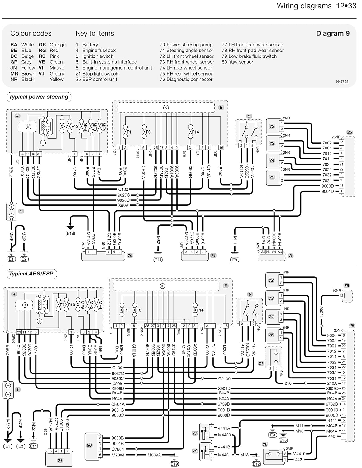
Figure 5.3: Visual guide for uncliping securing clips, withdrawing the belt through the parcel shelf, and removing the tailgate trim.
Rear Parcel Shelf Removal
- Unclip the securing clips from along the rear parcel shelf.
- Withdraw the belt through the front of the parcel shelf trim panel.
- Undo the retaining screw from the grab handle.
Tailgate Trim Removal
- Undo the retaining screw and remove the pull strap from the tailgate.
- Unclip the luggage compartment light from the trim panel and disconnect the wiring connector.
- Release the plastic securing clips from the sides and the rear edge of the trim panel.
6. Утасны диаграм
This section contains detailed wiring diagrams to assist in diagnosing and repairing electrical systems. Each diagram includes a key to identify components and wire colors.

Зураг 6.1: Хуучинample of a wiring diagram, showing connections for typical power steering and ABS/ESP systems with color codes and component keys.
Key to Items:
- BA: Blue
- RG: Red/Green
- ЭСВЭЛ: Улбар шар
- GR: Grey
- VE: Green
- JN: Yellow/Brown
- MR: Brown/Red
- VJ: Green/Yellow
- NR: Black
Note: Full wiring diagrams and keys are provided within the manual for comprehensive electrical system troubleshooting.
7. Техникийн үзүүлэлтүүд
This section provides general specifications for the Peugeot 407 Diesel models covered by this manual.
- Нийтлэгч: ЖХ Хайнс ба ХХК
- Хэл: Англи
- ISBN-10: 0857339826
- ISBN-13: 978-0857339829
- Барааны жин: 2.31 фунт
- Хэмжээ: 8.27 x 0.79 x 10.63 инч
8. Алдаа засах
The manual includes sections dedicated to fault finding and diagnosis. These sections provide systematic approaches to identify the root cause of common vehicle problems, from engine issues to electrical faults. Refer to the specific chapters for detailed troubleshooting guides.
9. Баталгаат хугацаа ба дэмжлэг
This instruction manual is a third-party publication and does not come with a direct product warranty from the publisher. For vehicle-specific warranty information, please consult your Peugeot dealer or the official Peugeot owner's manual that came with your vehicle. For support regarding the content of this manual, please refer to the publisher's contact information typically found within the manual itself or on their official webсайт.